Exterior Photo of Building
Elevated ELF magnetic fields were present in a sizeable portion of the ground level floor of this commercial building in mid-town Manhattan.
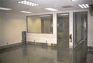
Photo Of Mail & Messenger Room Interior
The area of concern is the mail & messenger rooms located on the ground floor. The space is located immediately above the basement electrical facilities. The exterior office windows at the far end of the space were an architectural detail that the building owners wanted to preserve.
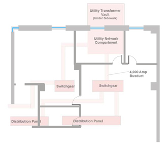
Basement Electrical Facilities With Ground Floor Office Plan Superimposed
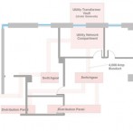
This superimposed view of the mailroom floor plan over the basement electrical facilities shows that the utility transformer vault is partly under the mailroom area and partly under the sidewalk and street. This illustrates that magnetic fields enter the mailroom from the basement and from the street into the mailroom through the exterior wall with windows.
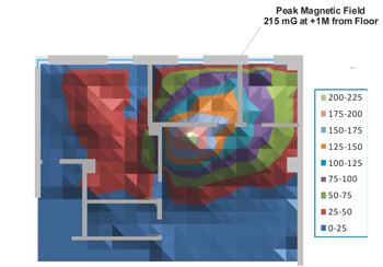
Contour Plot Of Magnetic Fields
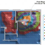
This contour plot shows the peak location of magnetic fields is in the mailroom immediately above the network protection vault with approximately 800 mG on the floor and 250 mG at one meter above the floor. The entire area has very sizable fields, averaging 40 mG – sufficient in strength to cause extreme computer monitor interference.
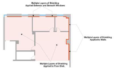
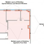
Shielding Floor Plan Diagram
All proposals for shielding the mailroom required the closing of the three exterior windows with shielding material. An alternate plan was developed by FMS to lower magnetic fields in the mailroom to a 10 mG maximum value by the installation of multiple layers of conductive and permeable material on a portion of the mailroom floor and on two wall surfaces, without closing the windows. Computer simulations of the proposed shielding scheme indicated that slightly elevated fields would remain in a very small area near the windows. Sufficiently small to allow for space planning to offset the small area of elevated fields.
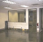
Photo Of Mailroom Interior With Shielding Installed
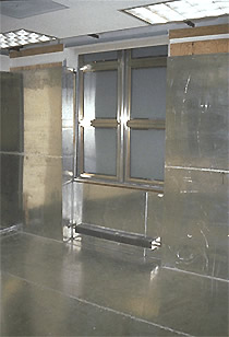
This is a partial view of the mailroom interior after shielding installation and prior to restoration of interior finishes. Note the wall shielding does not cover the exterior windows.
Interior Shield Photo by Window
This is the finished appearance of multiple layers of magnetic field shielding material installed on the wall, around window locations.
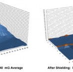
3D Plots of Magnetic Fields Before & After Shielding
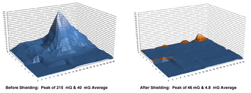
These are 3D plots of magnetic field conditions at one meter from the floor, in the mailroom area prior and after installation of the shielding scheme. Before shielding, the peak level was 215 mG and an average of 40 mG was present throughout the mailroom. The “After” 3-D plot of final magnetic field conditions indicate that after all FMS mitigation measures including shielding installation and reductions in “net current” circuit conditions were completed, the highest remaining field of 46 mG was present in an window area as anticipated, while the average was reduced from 40 mG to 5 mG throughout the mailroom. All EMI interference concerns were successfully eliminated.

Over its 20 years, FMS has successfully completed hundreds of EMI projects which included a diverse range of consulting and mitigation services.
Take a look at a list of the markets we serve »
