
 Exterior View of New NANO Research Laboratory
 Floor Plan of Sub-Basement Imaging Suites and Adjacent Power Systems
 Computer Simulation Studies of Power System Magnetic Field Emissions
 Sub-Basement Shielding Plan
 Finite Element Models of Shielding Plans
 Computer Simulation AC Magnetic Fields After Shielding Installation
 Dual Layer Duct Bank & Man Hole Shield Prefabrication
 Site Installation of Dual Layer Shielded Man Hole Enclosures
 Site Installation of Dual Layer Duct Bank Shielding Assemblies
 Final Site Installation of Dual Layer Duct Bank & Man Hole Assemblies
 Installation of Six Side Shielding in Three Imaging Suites
 Shielding of Transformer & Main Electrical Room and Feed Conduits
 Testing of Shielding with use of Temporary Load Banks
 Precision Test Equipment Utilized to Measure AC Magnetic Field Conditions
 Measurement Test Plan
 Typical Measurement Result in Fully Shielded Imaging Suite
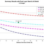
 Summary of AC Magnetic Field Measurements After Shielding Installation
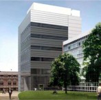
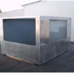
Exterior View of New NANO Research Laboratory
A major US university recently completed construction of an extensive NANO Technology Research facility. A large portion of the research facility is located in a large three level, subterranean complex containing ten advanced SEM/TEM Imaging Suites, Clean Room and other research labs.
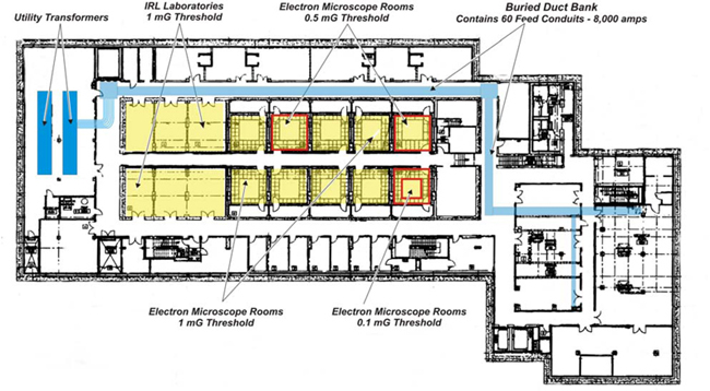
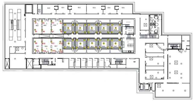
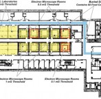
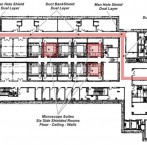
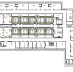
Floor Plan of Sub-Basement Imaging Suites and Adjacent Power Systems
This is the floor plan of the lowest level of the subterranean portion of the research facility which contains 10 Imaging Suites which will house a variety of advanced SEM and TEM instruments. Note that the AC magnetic field background threshold must not exceed 1 mG and that three Imaging Suites have more stringent requirements of 0.1 mG and 0.5 mG. Unfortunately, all of the microscope suites are located immediately adjacent to the building’s main utility transformer and distribution systems. Of particular concern is the very close adjacency of a buried electrical duct bank containing some 60 conduits with feed circuits totaling in excess of 8,000 amps.
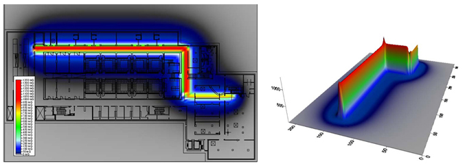
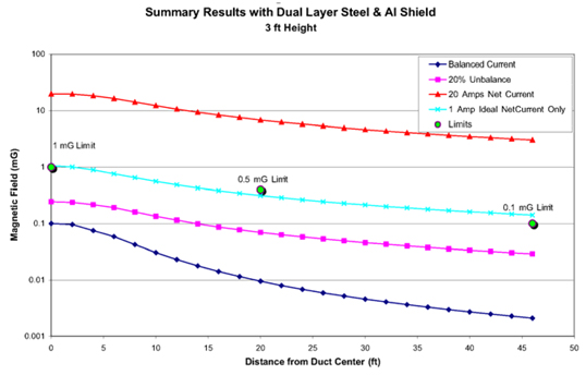
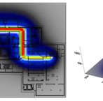
Computer Simulation Studies of Power System Magnetic Field Emissions
Extensive computer simulation studies of the sub-basement high current electrical distribution duct bank and adjacent main switchgear plus substation equipment provided a view of AC magnetic field levels likely to be present in the adjacent Imaging Suites upon completion of the building. AC magnetic fields ranging from 25 mG to >300 mG may be present in all of the Imaging Rooms; greatly exceeding the 0.1mG to 1mG threshold requirements.
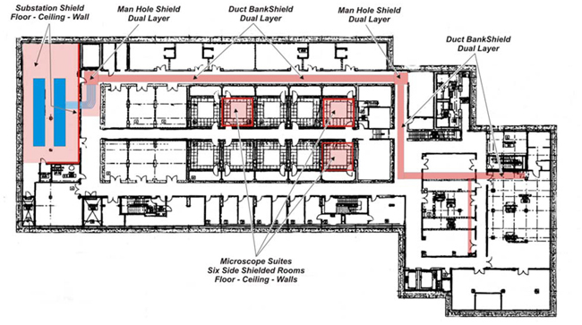
Sub-Basement Shielding Plan
Based on data from computer simulation studies, a robust shielding scheme was devised to reduce AC magnetic field emissions from the utility transformer vault and buried bus duct circuits which requires installation of conductive shielding on the entire floor, ceiling and two walls of the substation. A very robust multi layer shield consisting of low carbon steel plus aluminum, totally enclose the entire span of the buried electrical conduits plus two intermediate “man hole’ junction splice points. In addition, a layer of aluminum conductive shielding was to be installed on the floor, ceiling and all four walls in three of the microscope suites with stringent 0.5 mg and 0.1 mg threshold requirements.
Finite Element Models of Shielding Plans
Multiple, independent computer models utilizing Finite Element software, were constructed of the envisioned AC magnetic field shielding schemes to ensure that when installed, the shielding would be sufficient to reduce AC magnetic fields from the high current feed conduits and adjacent electrical equipment, to the most stringent < 0.1 mG EMI threshold.
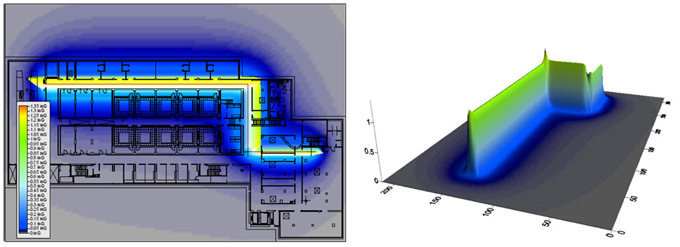
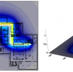
Computer Simulation AC Magnetic Fields After Shielding Installation
Utilizing data from the Finite Element computer models of the proposed shielding, these global simulation plots were generated to provide a visualization of AC magnetic field levels likely to remain after implementation of shielding measures, in all of the Imaging Suites and other adjacent research areas. All areas of EMI concern should have levels comfortably well below the 1 mG EMI threshold while the three critical Imaging Suites will also have levels well below the required 0.1 mG to 0.5 mG thresholds.
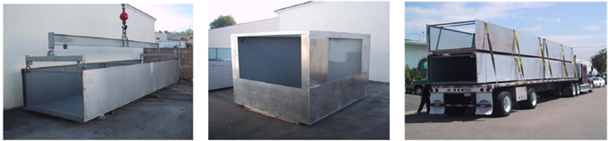
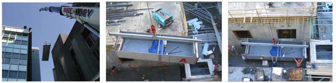
Dual Layer Duct Bank & Man Hole Shield Prefabrication
Thirty individual duct bank two layer shield enclosures were prefabricated in FMS’s Los Angeles facility. Each duct bank section measured 24 feet in length, 6 feet in width and 4 feet in height. Duct bank sections were shipped to the site and after installation of conduits, steel and aluminum covers plates are to be installed. Also, two “Man Hole” splice point assemblies were also prefabricated of aluminum and steel with openings to mate with duct bank sections. Each Man Hole measured approximately 12 feet in width by 10 feed in length and 8 feet in height. Four duct bank sections are shown loaded on a flatbed trailer for cross country transport to the building site.
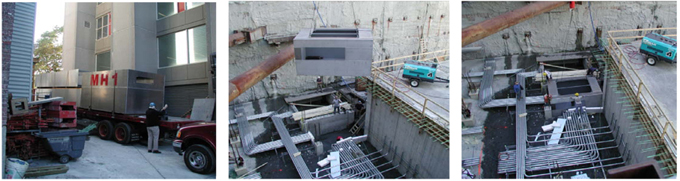
Site Installation of Dual Layer Shielded Man Hole Enclosures
This is the arrival of the first shipment of duct bank sections and man hole enclosure at the building side and preparations to hoist the first man hole into position. A 165 ton capacity crane was required to hoist the man hole and duct bank shielded sections. These photos show the hoisting and positioning of the first manhole assembly into position.
Site Installation of Dual Layer Duct Bank Shielding Assemblies
Next….hoisting of the first 24 foot long shielded duct bank section into position and mating with the shielded man hole assembly. Individual sections had to be hoisted over an adjacent six story building to the construction site. These photos show the first duct bank shielding section being positioned and mating to the first shielded man hole assembly.
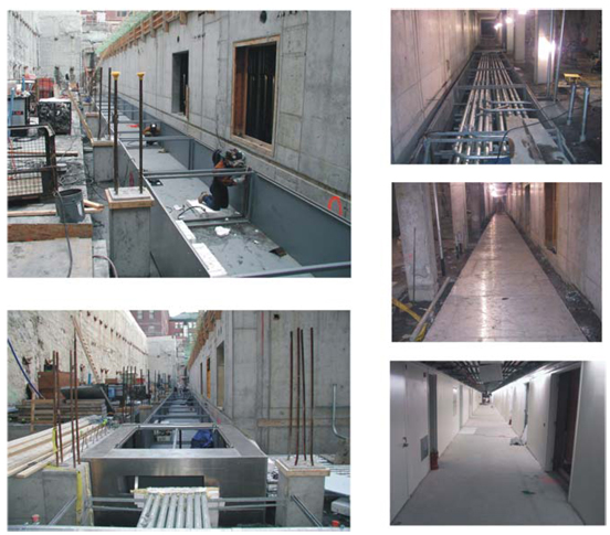
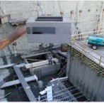
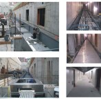
Final Site Installation of Dual Layer Duct Bank & Man Hole Assemblies
After all shielded duct bank sections were hoisted into position and joined…..individual sections were bonded together with a special welding procedure. Feeder conduits were then installed in the two layer duct bank shields. The interior of the duct bank shield was ultimately filled with concrete and then individual steel and aluminum shielding cover plates installed. Note hallway view with finished flooring poured on top of the buried shielded duct bank and man hole assemblies.
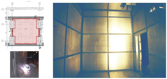
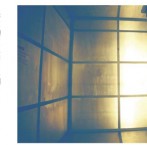
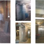
Installation of Six Side Shielding in Three Imaging Suites
To ensure that very low AC magnetic field levels of 0.1 to 0.5 mG where achieved in the three designated Imaging Suites, supplemental conductive shielding material was also install on each room’s walls, ceiling and floor surfaces prior to the finishing and fit out of the Imaging Suites
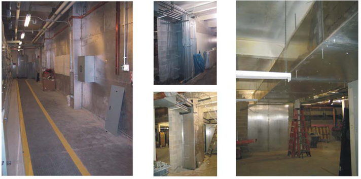
Shielding of Transformer & Main Electrical Room and Feed Conduits
As shown on the facility shielding plan, conductive shielding was also installed during construction of the building, on the floor, ceiling and two walls of the utility transformer and main electrical room located on the sub-basement level, adjacent to the Imaging Rooms. Supplemental shielding was also installed around main feed conduits rising from the sub-basement electrical distribution equipment, to extensive MEP systems and equipment associated with operation of the large clean room located above the sub-basement Imaging Rooms.
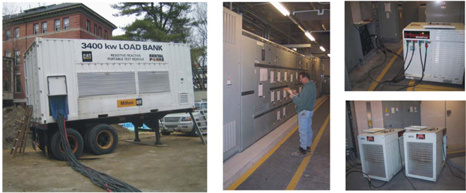
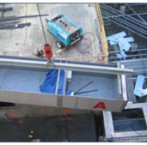
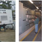
Testing of Shielding with use of Temporary Load Banks
To verify that the stringent AC magnetic field requirements had been achieved prior to future occupancy of the building and establishment of anticipated electrical loading conditions, a testing plan was devised by FMS and the project’s electrical contractor, which required the temporary connection of a 3400 kW load bank to circuits contained in the main feeder duct bank to provide surrogate loading conditions and to enable measurements of magnetic fields in all areas of concern. Multiple, smaller load banks were also used to exercise loading conditions on other feed circuits.
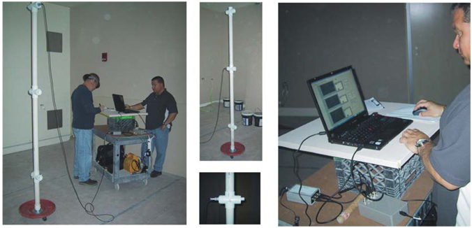
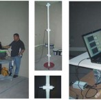
Precision Test Equipment Utilized to Measure AC Magnetic Field Conditions
With temporary loading conditions established precision test and measurement equipment capable of making highly accurate measurements (within 1% at 60Hz for magnetic field strengths between 0.01 mG and 10 mG) was employed to verify AC magnetic field levels in all ten of the Imaging Suites.
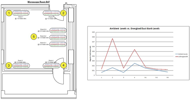
Measurement Test Plan
During the test period, multiple AC magnetic field measurements were made in each of the Ten Imaging Suites at each room’s corner plus in the center of the room which is the most critical location for operation of TEM & SEM microscopes. Measurements in each of these locations were also made at three different elevations.
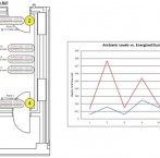
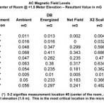
Typical Measurement Result in Fully Shielded Imaging Suite
This measurement data for one of the fully shielded Imaging Suites indicates that during the test period, AC magnetic field levels in the center of the room (most critical area) were < 0.02 mG at all measurement elevations…..substantially well below the required 0.1 mG EMI threshold.
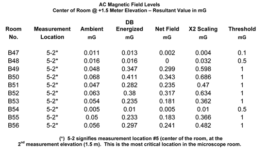
Summary of AC Magnetic Field Measurements After Shielding Installation
This table provides a summary of AC magnetic field levels documented in each of the ten Imaging Suites during the test period. Note, that AC magnetic field conditions in each of the ten Imaging Suites were reduced to levels significantly well below the target EMI thresholds of 0.1 to 1 mG even with the application of a X2 “scaling factor” as a safety margin for unanticipated future increases in loading conditions. The Center for NanoScale Systems has subsequently been completed, occupied and sensitive microscopes are operating without EMI interference concerns from AC magnetic fields

Over its 20 years, FMS has successfully completed hundreds of EMI projects which included a diverse range of consulting and mitigation services.
Take a look at a list of the markets we serve »
New York, NY 10065 Phone: (212) 628-6860
Fredericksburg, VA 22408 Phone: (212) 628-6860